
Fan Motor Selection: Key Factors to Consider
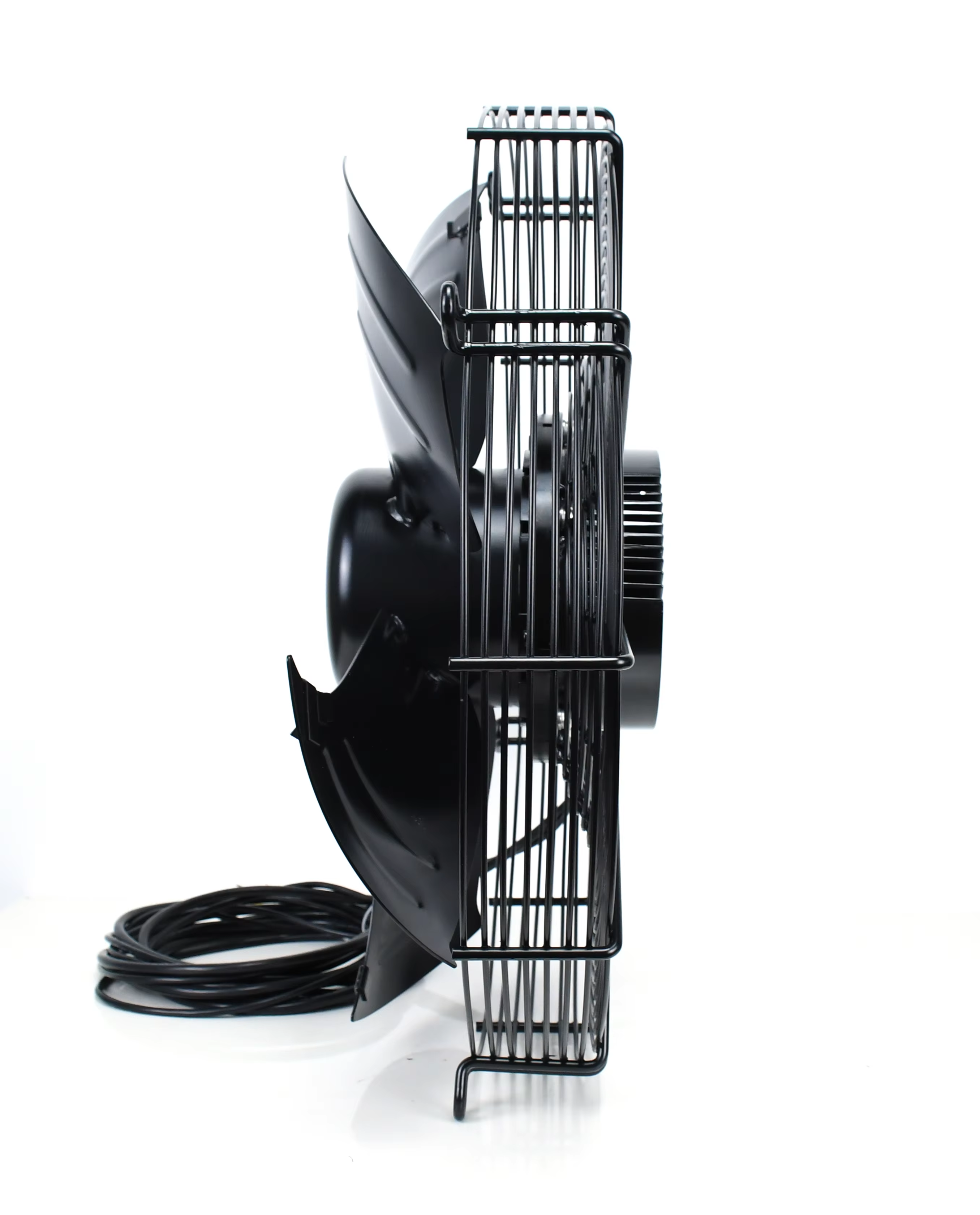
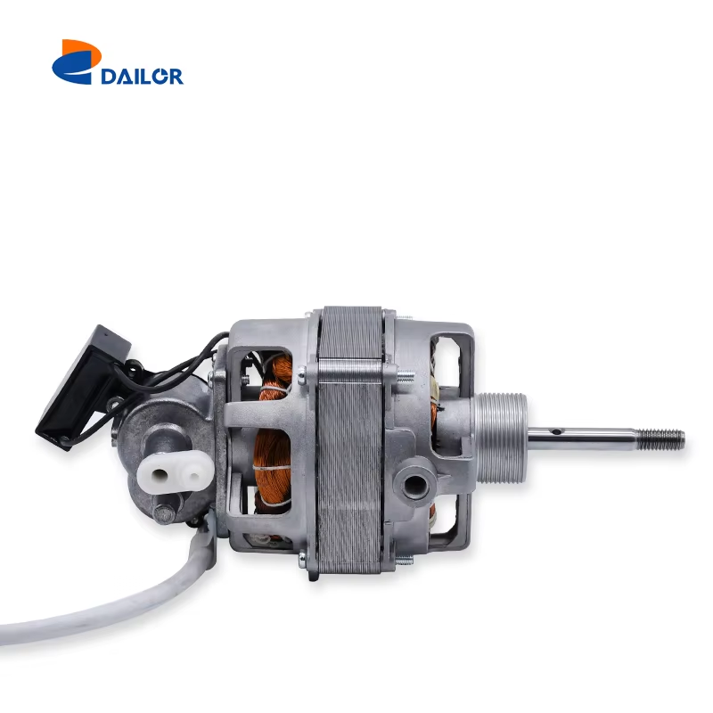
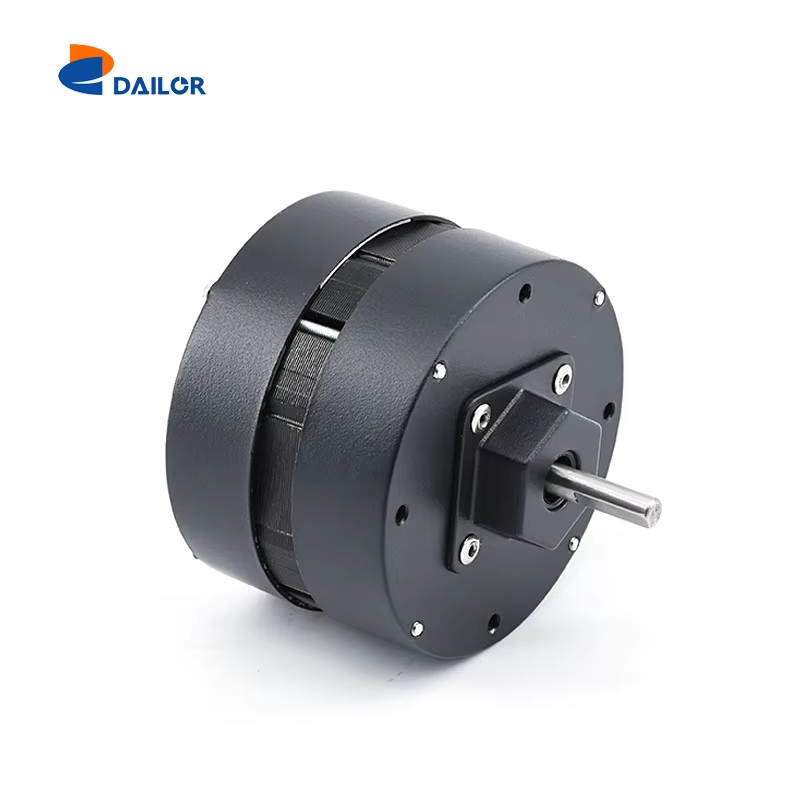
Understanding Fan Motor Types and Their Applications
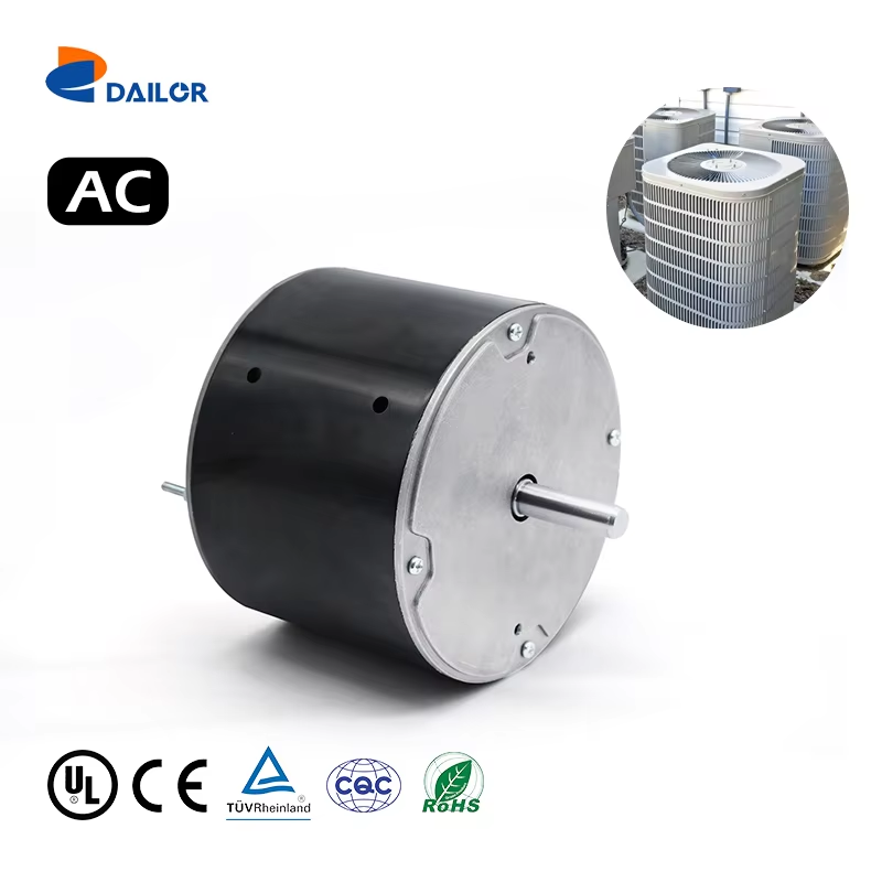
AC vs. DC Motors in Modern Systems
AC (the Alternating Current) and DC (Direct Current) motors are what in mixer language is exactly what i wrote above, one for each system, even in a raw dou...
View More